Guide to Automating Switch Configuration with Jinja2 Templates
Configuring a group of switches manually can be tedious, time-consuming, and error-prone task. Yet, with Jinja2 templates, you can easily automate this process and ensure that the configuration is consistent across all switches. Jinja2 is a simple and powerful Python-based templating language that has become the de facto standard for network configuration.
This article will show you how to use Jinja2 templates to automate the configuration of a group of switches. We will begin by providing an overview of Jinja2 templates and how they can be used in Ansible. We will then provide step-by-step instructions on how to create a Jinja2 template and use it to configure a group of switches. Finally, we will provide some additional resources that can be used to learn more about Jinja2 templates and Ansible.
Let’s get started…
4 Steps To Develop & Deploy Ansible Jinja2 Template
- Identify specific feature configuration for two spine or leaf switches
- Identify switch specific configuration
- Write Jinja2 template with variables for switch specific configuration
- Automate configuration for group of switches using Jinja2 Template in AmpCon with Context Data (value for variables)
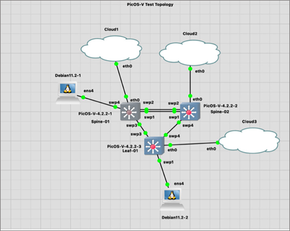
The MLAG configuration used in the Spine-01 and Spine-02 PicOS-V switches are given below.
Let us say we need to automate configuration of MLAG Feature in group of PicOS-V Spine switches (Spine-01 and Spine-02) represented in the following topology:
Step 1: Identify Configuration for Two Spine Switches
|
Spine-01 PicOS-V Switch Configuration |
Spine-02 PicOS-V Switch Configuration |
|
set interface aggregate-ethernet ae1 aggregated-ether-options lacp enable true |
set interface aggregate-ethernet ae1 aggregated-ether-options lacp enable true set ip routing enable true |
Step 2: Identify Switch Specific Configuration
When you compare the above two switches MLAG configuration, you will find most of the configuration lines are the same between the spine switches. Only a few lines of configuration vary between both switches, and are easy to identify.
Reference the highlights in the above step. The differing variables in each context data are summarized in the table below:
| Variable Name | Spine-01 Switch: Context Data Value | Spine-02 Switch: Context Data Value |
| hostname | spine-01 | spine-02 |
| my_mlag_node_num | 0 | 1 |
| my_mlag_ip | 10.10.0.1 | 10.10.0.2 |
| my_mlag_peer_ip | 10.10.0.2 | 10.10.0.1 |
Step 3: Write Jinja2 Template with Variables
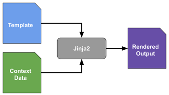
The top portion of the Jinja2 template consists of configuration lines with variables. Jinja2 uses double curly braces to signify variables. The bottom portion of the Jinja2 Template has variables definition (context data).
ⓘ For more info, refer to Appendix A – Jinja2 Template to Configure MLAG in Spine PicOS-V Switches.
Step 4: Automate Configuration for Group of Switches using Jinja2 Template in AmpCon
Using AmpCon, a network controller from Pica8 for multi-vendor networks, we can automate configuration of MLAG feature in a spine and leaf cluster using PicOS-V switches by completing the following steps:
- Upload template
- Create config for each spine
- Push config to spine(s)
Two-minute video tutorial
ⓘ For more detailed step-by-step example, refer to “Automate Configuration of MLAG Feature in PicOS-V Switches” on page six.
Benefits of Using Jinja2 Templates to Automate Switch Configuration
Jinja2 templates offer a number of benefits over manual configuration of switches, including:
- Automation saves you time and effort
- Easily scale the configuration of a large number of switches
- Eliminate downtime caused by config errors
- Flexible across a variety of switches
- Improved consistency across switches
If you are looking for a way to automate the configuration of your switches, Jinja2 templates are a powerful tool that can help you to save time, reduce errors, and improve the consistency of your configurations. Coupled with PicOS and AmpCon, network management has never been more flexible, resilient, and efficient. Get started with a free trial of PicOS-V today.


Mani Subramanian is Senior Technical Product Manager for Pica8.